ID-5100 modifications
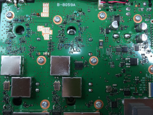
As ICOM doesn’t provide any information concerning TX/RX (MARS/CAP) modifications for the new ID-5100 I investigated the detailed function of the diode matrix responsible for the localization.
Due to the absence of any circuit diagram and the non-descriptive PCB I can’t tell the diode numbers – I can only show them.
To get access to the PCB only the lower cover needs to be removed (8 screws).
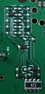
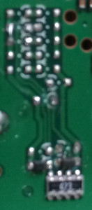
The upper 3 diodes need to be removed in order to gain „full functionality“.


before and after the modification
The left picture shows the standard configuration for an IC-5100E that is intended for german use.
( 1 ) ( 2 )
( 3* ) ( 4 )
( 5 ) ( 6 )
( 7 ) ( 8 )
( 9 ) ( 10 )
( 11 )
( 12* )
( 13 ) ( 14* )
( 15* ) ( 16* )
* -> installed by default
3 -> TX 70cm ext.
12 -> Crossband
14 -> TX 2m ext.
15 -> the removal converts the transceiver into the japanese version
16 -> the removal converts the transceiver into the american version (IC-5100A)